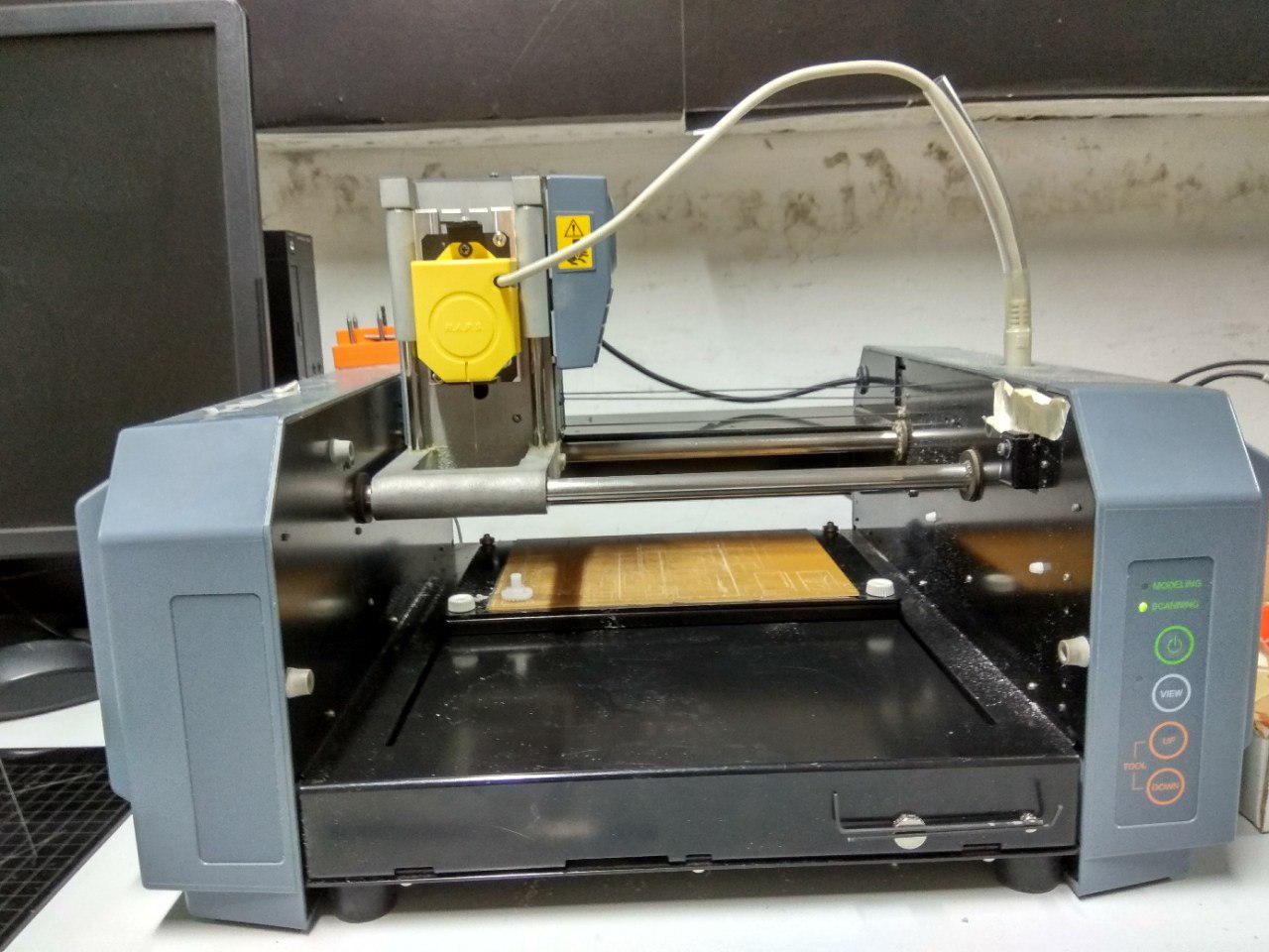
Roland Modela MDX-20 3D Milling Machine
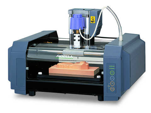
The Roland Modela MDX-20 is a desktop 3D scanning and milling machine that is compatable with many popular 3D CAD software.The machine can be used to mill ABS,a crylic, wood, plaster,styrene foam, chemical wood, wax, and light metals such as aluminum and brass. The Modela Software can accept .STL, .DXF and .MDJ file types , and we can also use Fab Modes to work with these files for milling and scanning .
Specifications :
- Maximum Working Area: 203.2 mm (X) x 152.4 mm (Y) x 60.5 mm (Z)
- Maximum Table Load Weight: 1 kg (2.2 lbs)
- Compatible Materials: ABS,acrylic, wood, plaster, styrene foam, chemical wood, wax, plaster, polyacetal, ploycarbonate , Sandomur SS , aluminum, brass
- Weight of Unit: 13.7 kg (30.2 lbs)
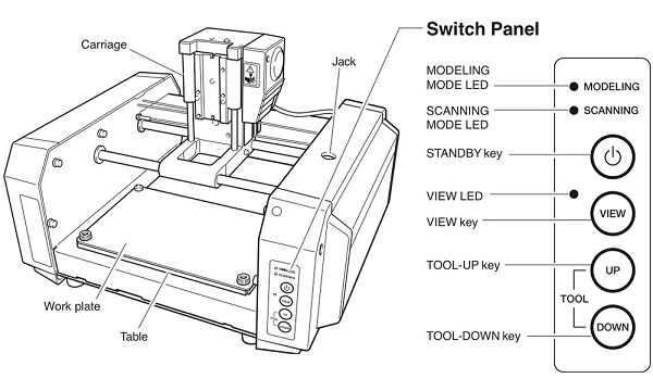
HOW IT’S WORK (MODELLA MDX 20)….?
Modella is like an ordinary 3-Axis CNC machines, Each axis is driven by a stepper motor and the cutting program tells the machine where to go by giving coordinates by G.code to the machine in real time.
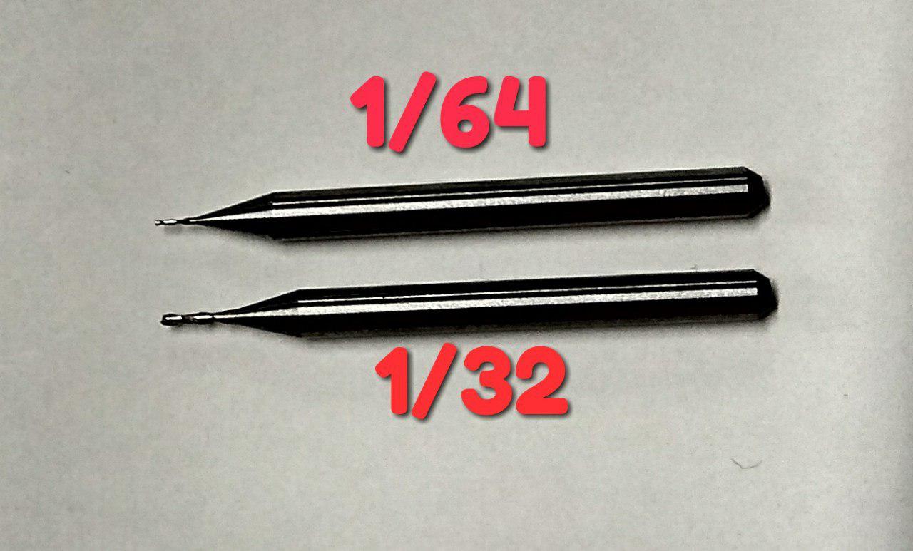
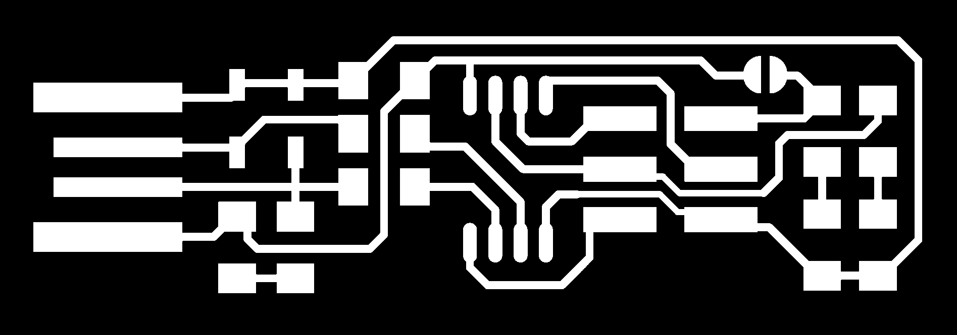
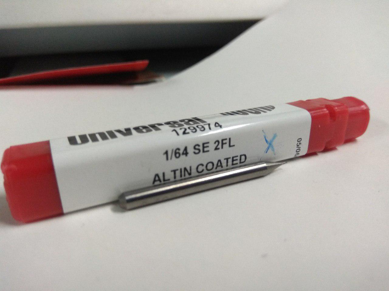
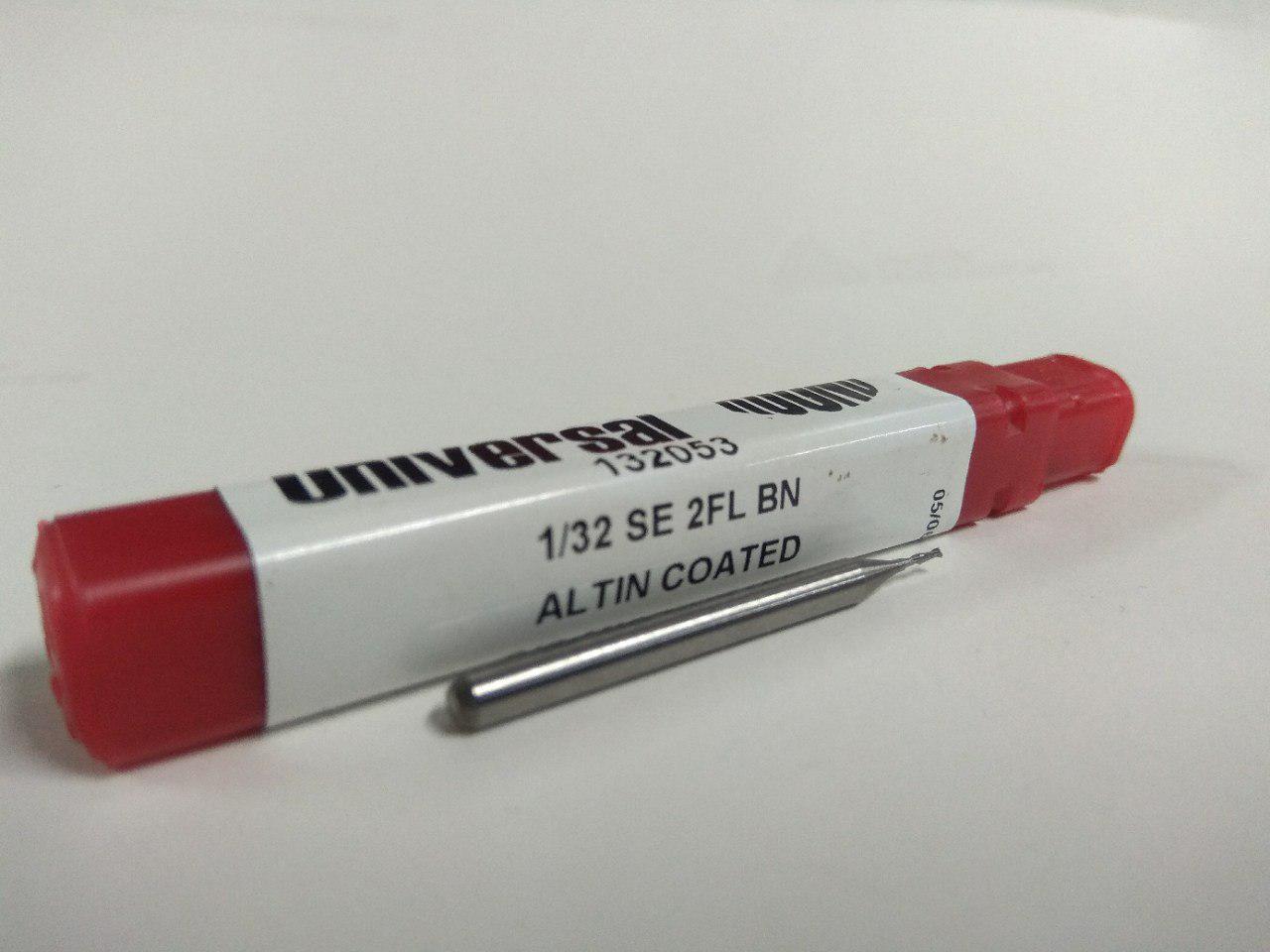
The Fab Module software will convert .png image in to a we series of tool paths, these tool paths are defined by their coordinates and G-code. The .png image is a black and white layout of the board, and the black portions will be milled and the white portion is where the copper will be left. We have two processes in making a PCB, The first one is milling the traces to get the circuit board pattern, and the second is cutting out the board from the base copper clad and For milling traces, we use the 1/64 inch (0.4mm) bit and for cutting 1/32 (0.8mm) inch bit.i’ll examplain all things one by one.
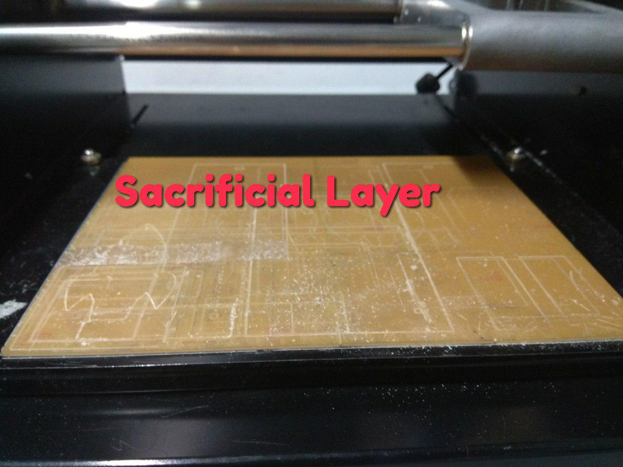
SETTING UP THE MACHINE
-
First Make sure to use some Sacrificial material on top of the bare metal base , it will prevent the damage of bit or the machine’s table.
-
Check the Drilling bit’s , first we need mill the trace then cut,and make sure to use the correct bit.when we start to mill trace check the bit because the previous person will cut his board with cutting bit and that will be the default when we start to work.
-
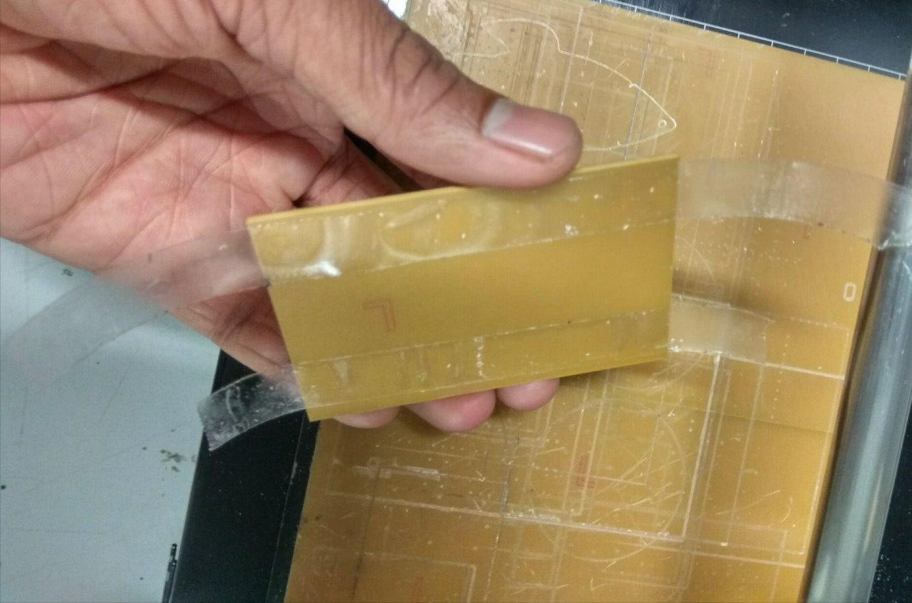
Fix the PCB on top of the Sacrificial layer, better to use a double sided tape
-
For tighten the bit ,first click view then the table should come out and the head will move to the far right,now load the bit you want to use, for milling traces, we use the 1/64 inch bit and for cutting 1/32 inch bit. Now insert the bit and use the Allen key to tighten the screw. Make sure it is tight on both sides.
-
For Move the (0,0) Position click the View mode again.
-
Now Set the X’axis and Y’axis for by clicking on move to Xmin and Ymin on the Fab Module.
-
Before starting Milling check your speed and depth settings and the tool position on the fab modules window.
PCB FABRICATION
Here we are going to make a FabISP.First Download the Milling and Cutting Schematics here
-
Trace
-
Outline cutout

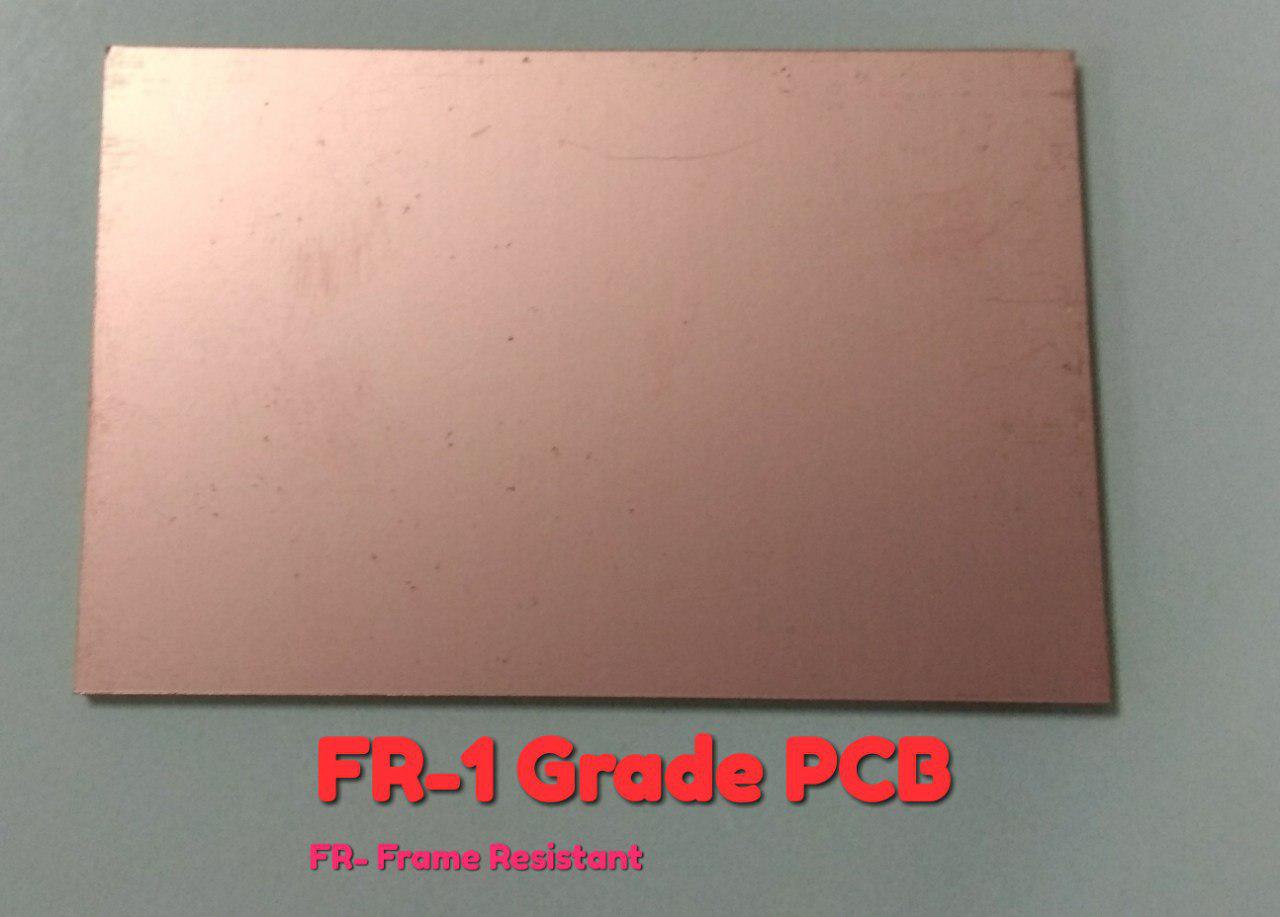
We are using FR-1 Grade PCB.
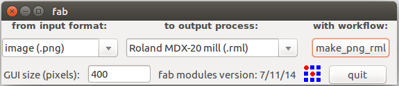
open Fab Modules by typing fab on linux terminal or you can use the online version.
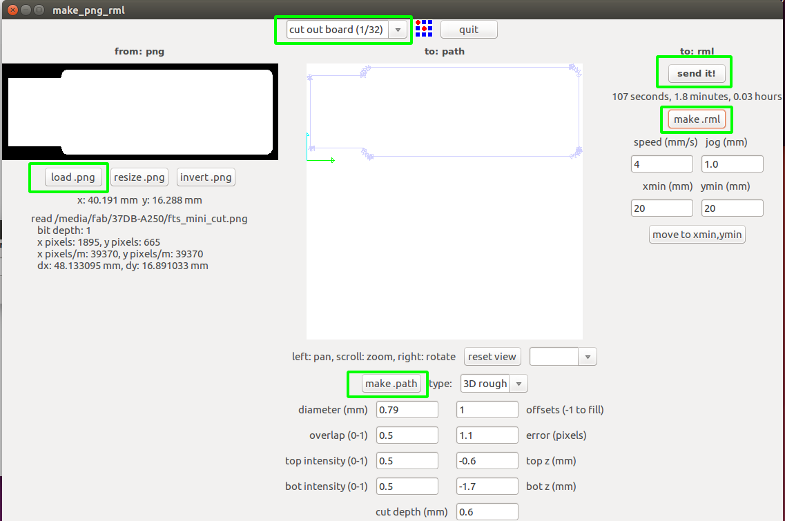
In Fab Module Select Image(.png) as Input and Roland MDX-20 mill(rml) as ouput Process and Click make_png_rml .
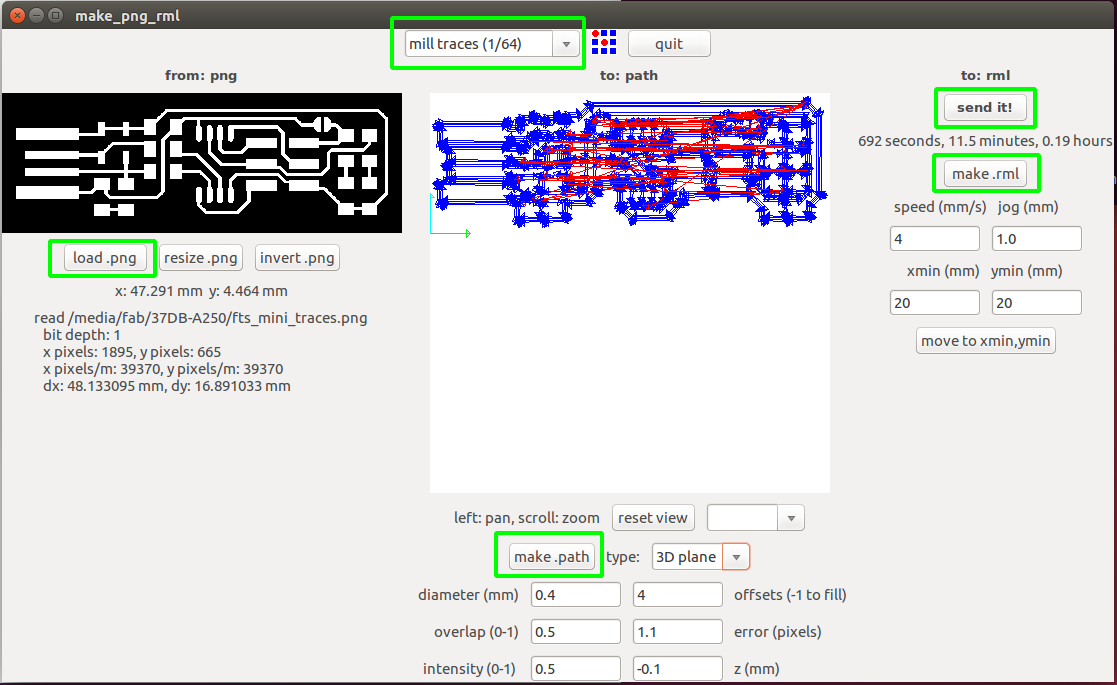
Now Fab Module will open a new window, and here we need to image for milling by clicking load.png , and don’t forget to select the mill trace (1/64) for milling and click the make.path to create path for milling.
Now set the ‘X’axis and ‘Y’axis
First clik the View button on the Modela Control panel.
Now change the bit ,For milling we use 1/64 bit.
After tighten the bit, click the View button to get back to Home position.
Now set the Correct X and Y axis based on our PCB board Position.
For setting Z’axis ,set the x and y then by using UP and Down button just stop the nearby the PCB and then losen the ‘Bit’ and tight it when it’s touch the PCB , that’s all we now set the Z axis.
Note :- Don’t forget the X and Y axis.if we face any issue like power failure of application forzen we can’t start it same postion without the X and Y axis.
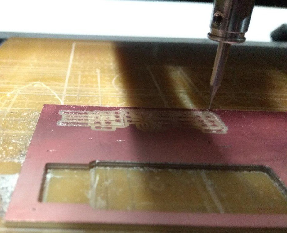
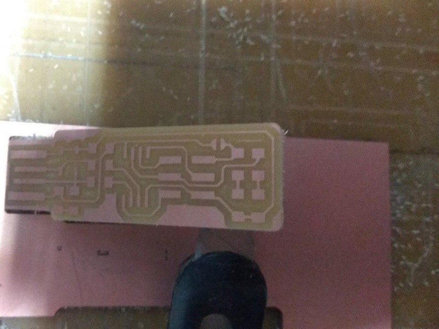
Now Click Make.rml to genrate instruction after that click Send it ! to start Milling.
Now we successfully milled the Trace
Next Cut the Trace, First change the Bit,For Cutting we use 1/32
so first load the Image in Fab Module and make the path after that send it to machine to cutting
make sure to set the bit as the cut board(1/32) and do the same that we did for milling , make.path and make.rml and start process by clicking Send it!
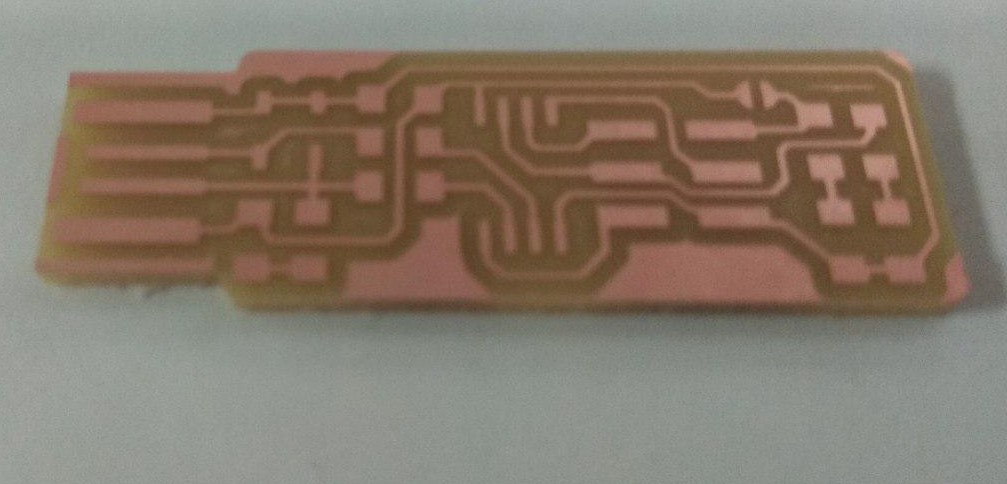
We successfully completed cuting .
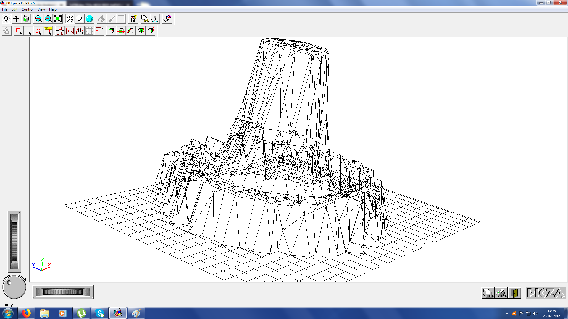
3D Scanning
3D Scanning is a process to convert Real 3D object to computer File.it’s opposit process of 3D Design .Today there somany 3D Scanner’s avilable Depthsensor like Micorsoft Kinect and Intel Real-Sense is a good Example.
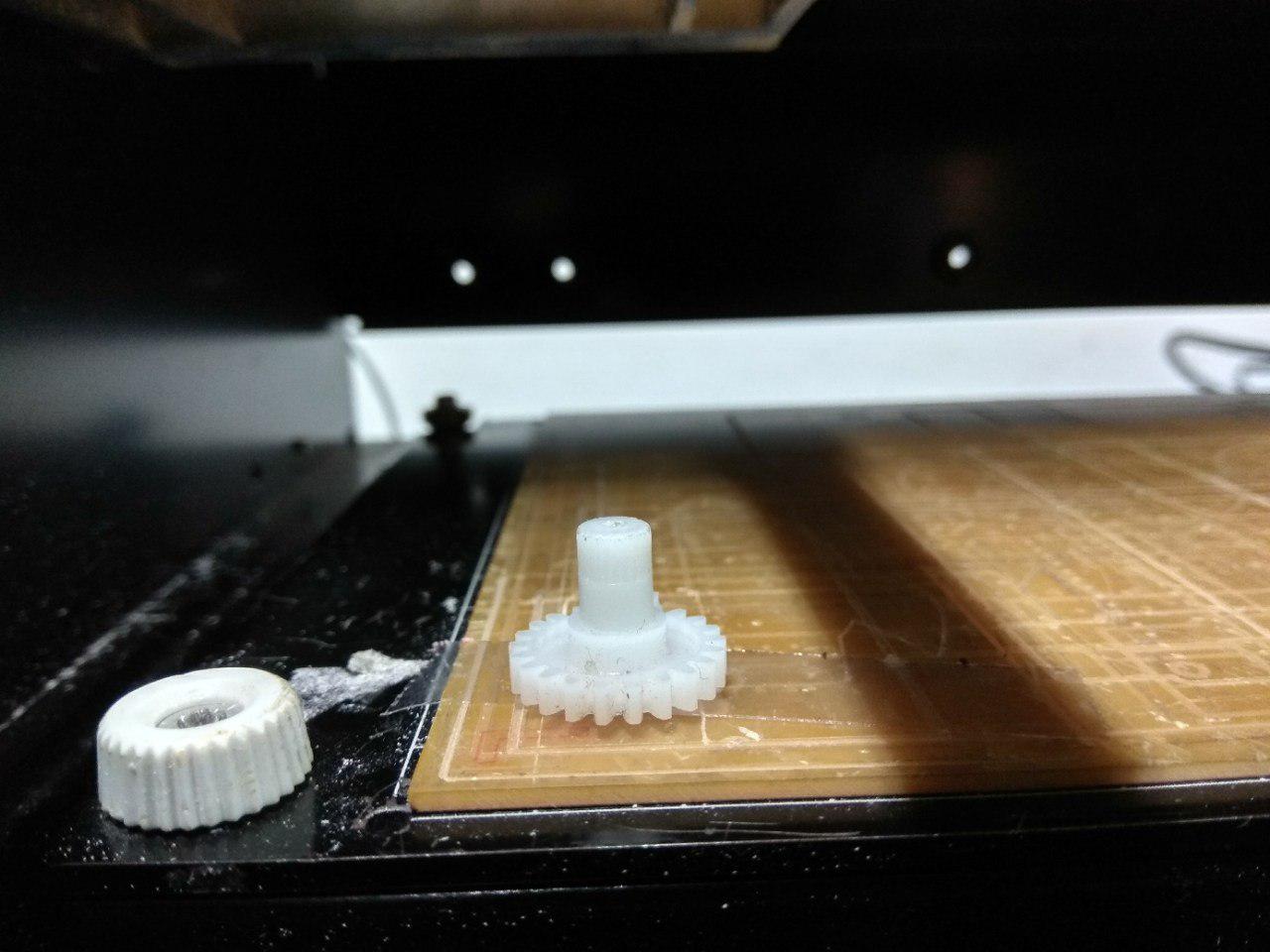
the same modela we are using for Scan 3D object. but in here we changed the milling head to Scanning head.
Setting the Machine
-
First i Fixed the gear on the Scarificial layer using double tape insulation.
-
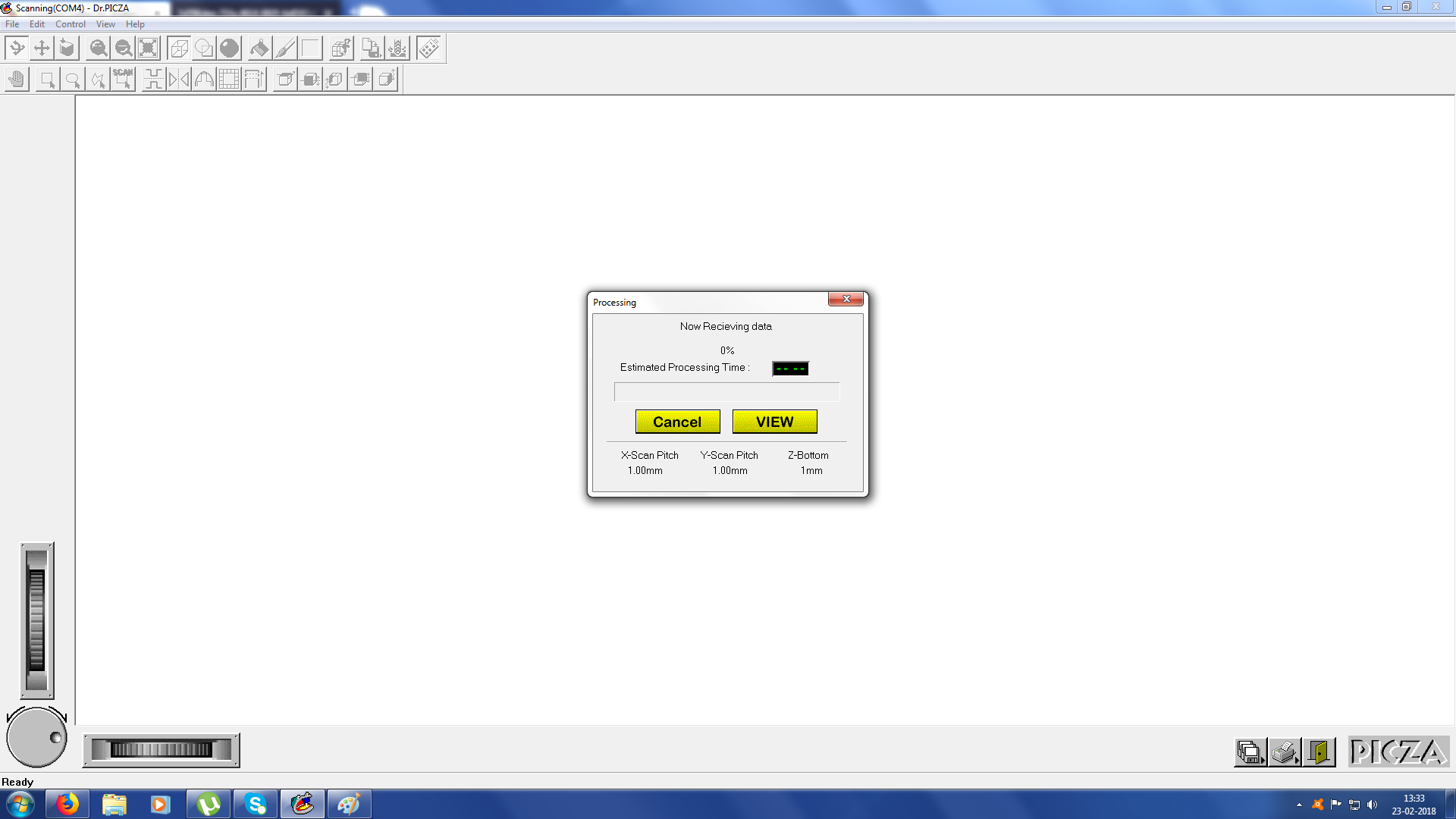
We can use Dr.PICZA software to scan with Modela.
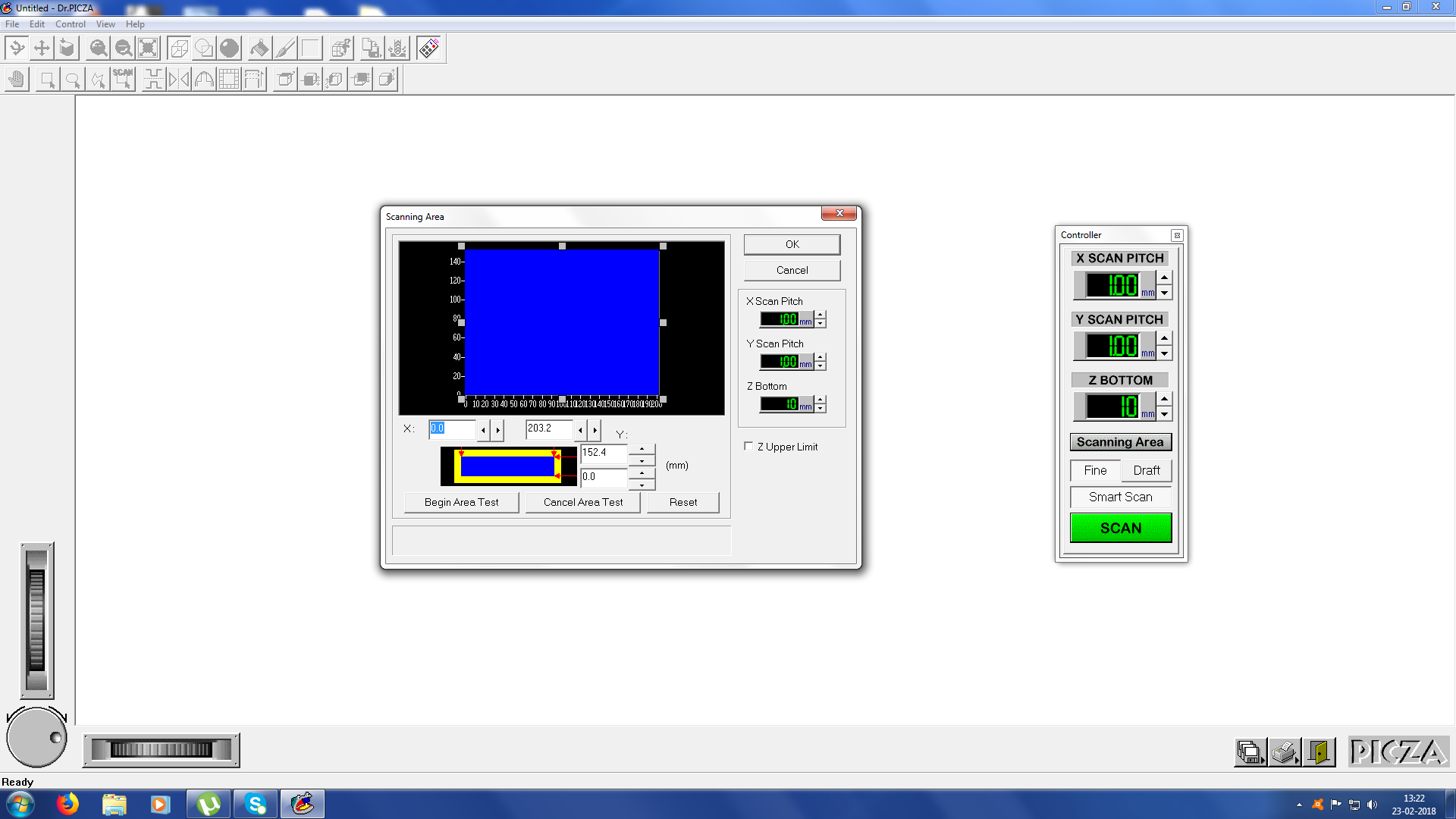
-
First we need to set the scanning area for calibrating the Sensor and Software.
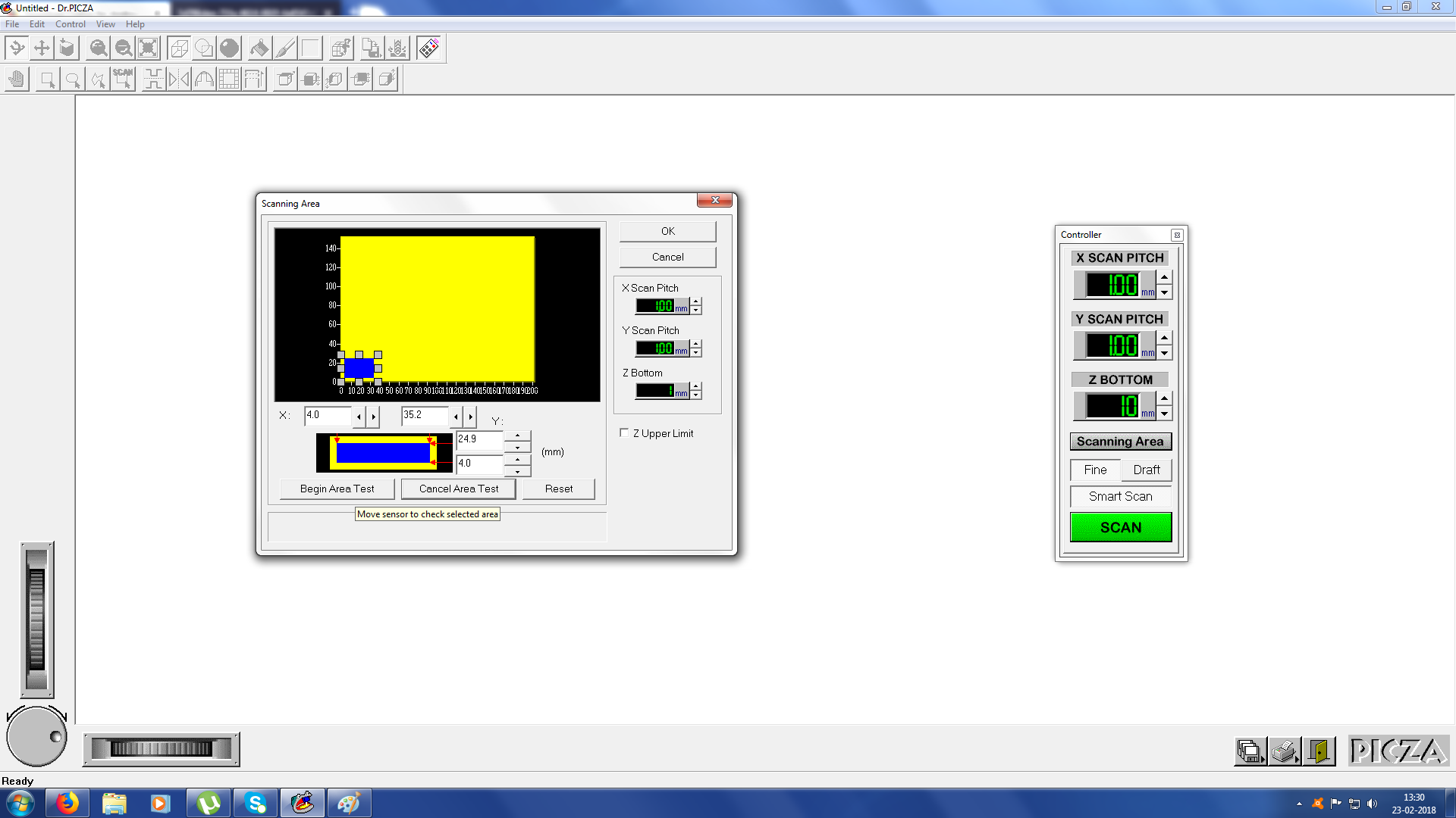
So here the Blue area is the Scanning Area and the Yellow is the tottal Ground Area.
-
After that we can test the Area by using the begin Test Area option after that i started scanning.
-
Scanning Process
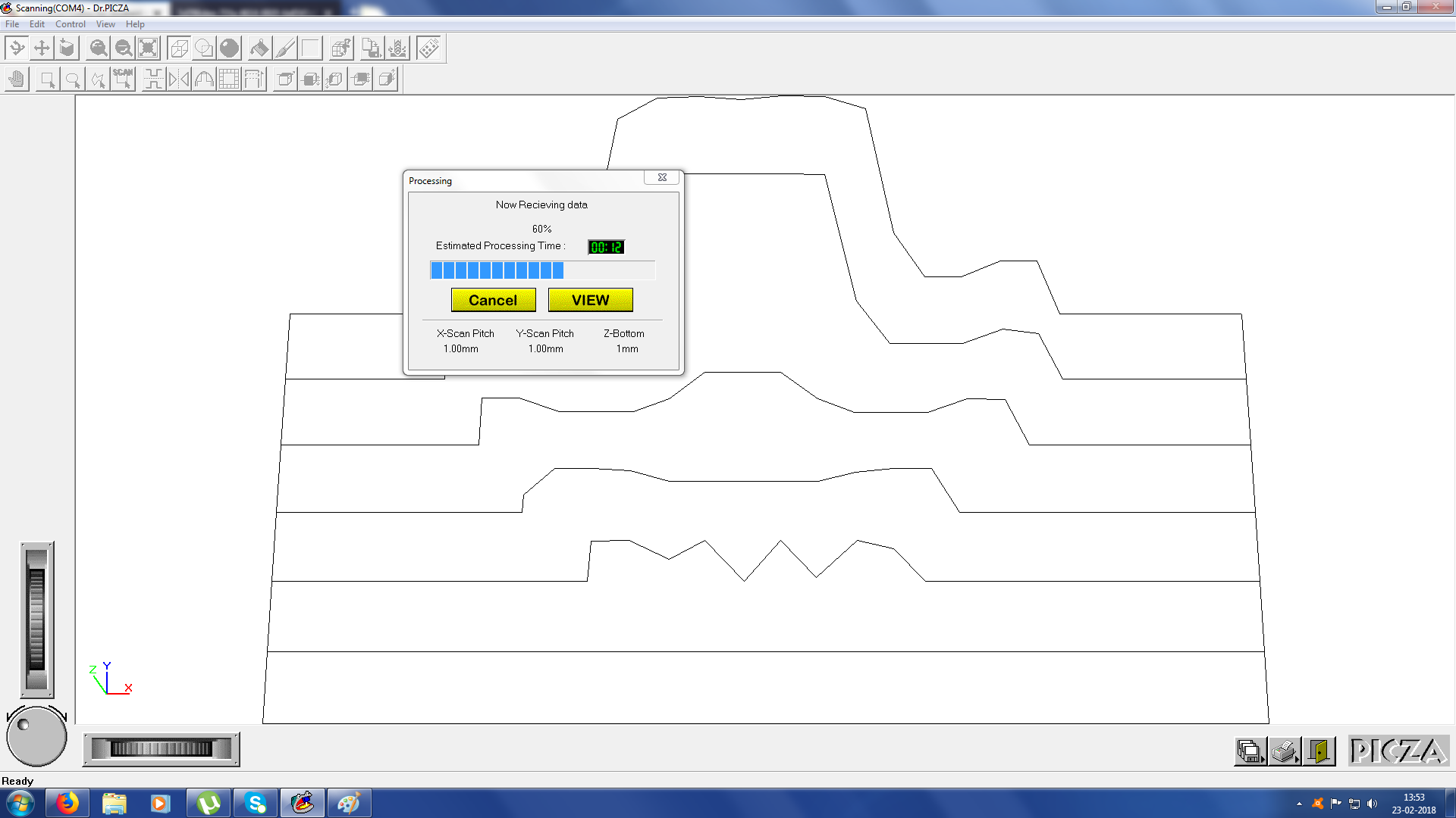
It will take time to scan the whole area one by one as layer.